
Tags
Quite some time ago, I posted about this on my main blog, but it has occurred to me that, firstly, it might be time for an update, and secondly, that a post about why computers use 1s and 0s is better suited here on my programming blog. (Especially as this is the 101st post!)
It turns out there is a very good reason computers use 1s and 0s, and while it is possible to use other numbers, the 1s and 0s are all that is needed.
To see why, imagine (the imaginary) Alex and Blair. They stand on different hills on either side of a river. It’s night — and a bit hazy! — but they intend to send messages to each other using flashlights. (The noise of the river makes it too loud for speech.)
They’ve devised a simple code matching numbers to letters: A=1, B=2, C=3, and so on to Z=26. They figure it’s hard to transmit the shapes or images of letters, but there are many ways to send the values of numbers.
The simplest is like the horse that (supposedly) adds. Tap once for one, twice for two, and so on. Prisoner’s hash marks count days one scratch at a time (but align them in groups of five to make counting a large number easier). Alex and Blair could send messages by flashing their light on and off as many times as needed for a given number. Noticeably longer pauses between would delimit numbers.
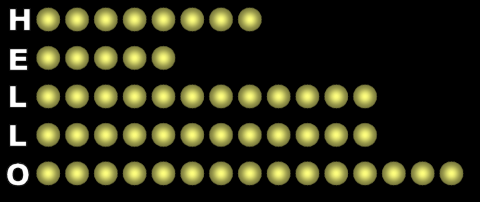
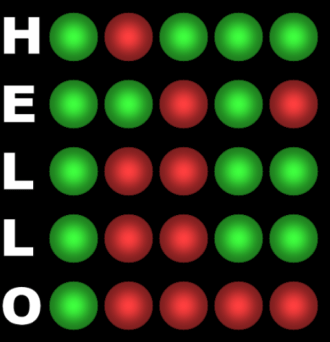
“HELLO” by counting the flashes…
It would work, but it would also take a long time and be incredibly tedious. Both need to keep careful track of the number of flashes for this to work. A miscount means a wrong number, and therefore a wrong letter.
§
At the other extreme, Alex and Blair might try to use precise dimmers on their flashlights to set them from 1 (almost off) to 26 (full brightness). This allows them to send a number with a single flash.
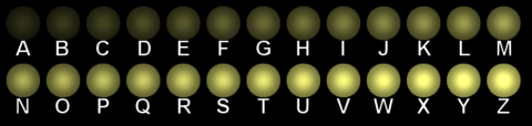
A through Z in 26 different brightness levels of light…
Great system in concept — very high information density — but virtually impossible to implement. Distinguishing twenty-six different levels of light isn’t a problem; camera sensors distinguish far more than that. Our eyes are even better at it. The problem is knowing whether a light value that appears to be 18 really is 18. It helps to have a reference to what light values of 1 and 26 look like, so maybe there are three flashlights: one set to 1, one set to 26, and one set to whatever number Alex or Blair are sending at the moment.
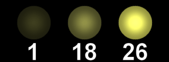
Even with reference lights (left & right), it’s hard to be certain the middle one is 18.
Recall that it’s a bit hazy for Alex and Blair, so light transmission is reduced. The flashlights themselves may be stronger or weaker than expected. Even if Alex and Blair carefully calibrate their signals, telling a light level of 18 from a light level of 16 or 20, let alone 17 or 19, is a huge challenge. There is an issue of linearity. Even with reference lights at 1 and 26, the levels must vary consistently (linearly).

“HELLO” using 26 levels of brightness.
Bottom line, the more levels a flashlight has, the harder it is to tell exactly which one it is actually showing. Firstly, because the more levels there are, the closer together they are and, thus, harder to distinguish reliably. Secondly, because the levels may not vary evenly (linearly), distinguishing them is even harder. We’re best off with as few levels as possible.
§
Since we’re already using multiple flashlights, why not just send actual number digits? If we use dimmers with ten positions, we can use one flashlight per number digit. With just two we can count all the way to 99. Distinguishing ten levels of light seems easier than trying to distinguish twenty-six.

0 through 9 in 10 different levels of light…
We have a new challenge now, though. We’re representing the “digits” 0 through 9, which suggests the flashlight might be off for 0 and fully on for 9. We might still want a reference light to calibrate the full-on 9 value, but there’s nothing to calibrate with a light that’s off. This presents a new calibration problem, though. If one flashlight is off and the other on, which digit is the on one, the first or second?
Multiple brightness levels are just plain tough. Let’s try something else. We can use different colors instead of different levels of brightness. If we use the color filters to specify values, our calibration problems are solved: It would be a challenge to distinguish 26 different colors, but ten seems doable:
- Red
- Orange
- Yellow
- Yellow-Green
- Green
- Cyan
- Light Blue
- Deep Blue
- Purple
- White
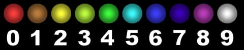
0 through 9 in 10 different colors of light…
There still seems some challenge among, say, yellow-green and green or the two blues. Sharp eyes are required.
§
Our system is getting better, but still has too much room for error. We’re on the right track, though. Let’s take the first lesson — minimal levels — to heart and use just two: green and red. Which means the only values are zero (green) or one (red).
This gives us the best chance of distinguishing levels. It’s pretty easy to distinguish between red and green. Or on and off. Or between lots of useful pairs of things (plus and minus voltage, spin up and down, left and right polarized, and so on).
Using only 1s and 0s — or on/off, or red/green, or up/down or whatever — is the easiest proposition for error-free data. Easiest to engineer, and easiest to use. The tradeoff is needing more “flashlights”. Let’s call them data channels.
With only two, there are only four combinations: green-green, green-red, red-green, and red-red. With only A, B, C, and D we won’t be able to send very good messages. (B,A,D and C,A,B might be helpful in warning someone or getting a ride to the airport).

Two lights × two colors = four combinations.
Fortunately, the number of possibilities doubles every time we add another flashlight. Three gives us eight red-green combinations, four gives us sixteen, five gives us thirty-two, and so on.
We could use five flashlights. Thirty-two red-green combinations is plenty for the twenty-six letters of the alphabet with six combinations left over for whatever. One obvious choice is a space (often given the zero value). We can assign whatever punctuation or control codes we like to the remaining five combinations.
“HELLO” using five green-red flashlights.
One trick we can use to expand our character set is to assign one of the combinations to a “shift code” that means all the other combinations now have new meanings until there is a second shift code to “unshift” back to the primary set. Doing this gives us at least sixty combinations we can assign to characters, digits, symbols, and control codes. (The notion is based on the Shift key on a keyboard. The Ctrl and Alt keys do something similar.)
§
Flashlights are inexpensive, so there’s no reason not to use more. Six gives us the same sixty-some possible combinations without bothering with shifting. But even if we allocate the entire 64 combinations to characters, it’s just enough for all 52 upper- and lower-case letters plus 10 digits plus a space (total 63). With just one slot left over, there’s no room for punctuation or symbols or control characters.
Seven flashlights, on the other hand, gives us 128 combinations, which is plenty for the English alphabet, the digits, lots of symbols, and plenty of control characters. Now our messages can use normal text and punctuation.
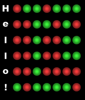
“Hello!” using seven green-red flashlights.
We might include an eighth flashlight for multiple reasons. For one thing, as we change the red and green filters for a new character, to avoid confusion, we should either turn the light off or (better yet) use an eighth light set to the side to signify that the pattern is currently not valid. (Leaving the lights on while changing helps the person watching not lose sight of the lights. Imagine they’re using binoculars or a telescope.)
We might also add an eighth light just to expand our possible combinations to whopping 256. Plenty of room for at least some other language characters, such as Ñ or Ø or Æ or Ä. With 256 combinations, we might even include some special-purpose characters, such as ¥ or © or §.
Now we’d might add a ninth light for synchronization. When the ninth light is red, the other eight lights are invalid and may change at any moment. When the ninth light is green, the other eight lights are stable — guaranteed to not change — and are valid. Basically, the synchronization light turning green means a new character (so pay attention to the pattern).
No need to put the lights in a row. Since we have nine of them now, a 3×3 grid makes compact sense. We can put the synchronization light in the center.
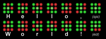
“Hello, World!” using nine green-red flashlights.
As shown, the center synch light is always green — each of the 3×3 groups shown are valid characters. In practice, the center light would turn red, the outer lights would change to the next character, and then the center light would turn green again. Each cycle brings a new character.
§
Why stop at eight channels? Why not nine or ten?
At some point there is a trade-off between the number of flashlights and the growing number of combinations. With ten data channels (plus an eleventh synch channel) we have over a thousand different combinations (1024, to be precise). With twenty data channels, there are over one-million combinations. With thirty, there are over a billion. The number of data channels depends on how many combinations are desired.
[I always liked the idea of ten — 1000+ is way cooler than 256.]
When data channels are relatively cheap, such as inside hardware, designs can use lots of them, which allows the rapid exchange of large amounts of data. When data channels are expensive, such as in long distance transmission, it’s best to use the fewest possible. In some cases, only one flashlight is possible — perhaps the distance is large, and it’s only possible to distinguish a single red or green light.
§
Which perhaps still leaves not entirely answered the question, “Why 1s and 0s?” Isn’t something lost with just two numbers? Wouldn’t 0-9 be better than 0-1?
Firstly, given the difficulty of distinguishing ten different levels of light, color, voltage, or whatever, especially throughout the whole system, it’s vastly easier to stick to just some version of yes and no. From an electronics point of view, dealing with only two signal levels provides the best possible data integrity, which is vital in computation — any confusion about levels corrupts the computation (not a good thing when computing bank accounts or airplane autopilot navigation).
Secondly, most importantly, any number that can be expressed with 0-9 (base ten) can be expressed with 0-1 (base two). Or with 0-7 (base eight) or 0-15 (base sixteen) or whatever number base we prefer. Any number that can be expressed in one base can be expressed in any other base.
The ratio from using 0-9 to using 0-1 is approximately 3.3 (precisely, it’s log 2), so it takes a bit over three times as many green-red flashlights to send the same numbers as the ten-color system can. We round up, so it takes four two-color flashlights to express numbers up to 9 (which is red–green–green–red).
Using two ten-color flashlights to send the numbers 00 through 99 requires 2×3.3=6.6, which we round up to seven. So, it takes seven two-color flashlights to send the numbers up to 99:

Seven flashlights to send the number 99.
So, how many levels we use for each data channel only affects the number of channels needed to express a given number. Using more levels compacts more into each channel but makes the engineering far more complicated.
Bottom line: Two levels is best from an engineering and data integrity standpoint, and the only penalty is needing more data channels. The canonical number in computers these days is 8 for the smaller parallel systems with multiples of eight (16, 32, 64…) used in larger systems.
§ §
If it hasn’t been obvious all along, the flashlights represent the bits of a binary digital computer. (The qualification is necessary. Not all computers are digital, and not all that are use binary. But most of the things we call computers are and do.)
While the flashlights used color, these computers use electrical voltage, usually in one of two ways:
- Instead of green light, 0 volts or Negative voltage
- Instead of red light, 1 (or more) volts or Positive voltage
The most common being to equate zero with zero volts and one with some positive voltage. The second method requires a power supply to provide both negative and positive voltages, the first just needs one.
§
Lastly an aside: the notion of bits per baud doesn’t really apply to computers, so the term baud isn’t as common as it was in the days when computers connected through phone modems. But it does apply to the flashlights.
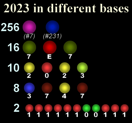
Different colored light systems with different bits per baud: 8, 4, 3⅓, 3, and 1 (top to bottom). The formula is: bits-per-baud=log2(#combinations).
A baud is the smallest unit of information in an exchange. In modern computers, a bit is the smallest unit, and because it has only two levels, it has just one bit of information:

So computers normally use one bit per baud. Which is why the term baud doesn’t come up with computers. It’s redundant: bits=bauds.
But a flashlight with 26 levels of brightness (or color) has:

With single flash it can send any number from 1 to 26. (And it does take, rounding up, five flashlights to express 26: red–red–green–red–green.)
A flashlight with 10 levels of brightness (or color) has:

Using two flashlights to express from 00 to 99 does have the sum, 6.6 bits per baud, but the notion of bauds applies to a single data channel. The math does work, though. As described above, it does take seven two-color flashlights to express 00 to 99.
And computers, likewise, need seven bits to count to 99. In fact, seven bits can count to 127 (including zero for a total of 128).
Ø

Post #101! (Which is only 5 in binary.)
And published on 10-11! (Which wasn’t planned.)
The clacks system in Terry Pratchett’s Discworld books works a lot like the example above with the 3×3 grid. Pratchett’s system is described as having a 2×3 grid, giving it six data channels (or bits).
So, the clacks system has six bits per baud and can send numbers from 0 to 63, which plenty for an alphabet, the number digits, and some other stuff.
Incidentally, the five-flashlight system closely resembles an actual early system for sending text, the Baudot code.
And the seven- and eight-flashlight systems, exactly match the early 7-bit and 8-bit ASCII codes.
Note that eight flashlights would suffice to send Unicode in UTF-8 form, so you could send any text in any language with no workarounds. (Sending Unicode in its purest form would take 21 flashlights!)